PARTI-Pucks: Puck-based data transmission using Adaptive Radio modems for Through-Ice communications

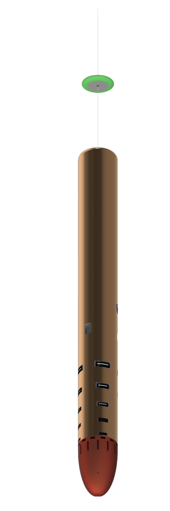
Concept of a Cryobot with an
RF communications puck deployed.
The PARTI-Pucks project, funded by the NASA COLDTech Program, aims to advance through-ice communication technology for a Europa subsurface mission, focusing on radio transceivers as the backup communication system to the primary fiber optic tether. Given Europa’s two primary thermal ice layers – a brittle cryogenic surface and a warmer convecting sub-layer – the project evaluates three communication designs: VHF/UHF (patch antennas), MF/HF (dipole antennas), and HF (crossed-loop antennas). These designs fit within anticipated mission constraints. In-ice tests on a glacier will bring the VHF/UHF and HF technologies to TRL 5, while in-air field tests will advance the MF/HF design to TRL 4.
Background
RF signal attenuation in ice is affected by temperature and impurities, restricting transmission distances. VHF/UHF signals may face challenges near Europa’s ocean due to increased attenuation, reflections, and scattering. Mission designs necessitate multiple transmitters and consider cryobot size and power for through-ice missions. Current proposals feature 1 GHz antennas with radio-isotope generators, but adaptations may be needed for varying ice conditions. Integrating puck communication with the cryobot’s design is vital.
Lower RF frequencies are more effective in imperfect ice, especially in colder conditions. VHF/UHF is optimal for upper ice layers due to minimized interference from Jupiter’s emissions and less attenuation. Deeper, the warmer ice affects VHF/UHF transmission, but MF/HF frequencies persist. The project’s goal is to design communication systems based on ice depth. In areas with dominant Jupiter noise, VHF/UHF pucks are recommended. As pucks go deeper and the noise decreases, the focus shifts to MF/HF or HF designs. Near the ocean, communication may depend on physical or acoustic links.
MF/HF Dipole Antenna
The Dipole Antenna prototype design consists of two insulated wires embedded in a tether. This unusual “end fire” mode uses a quasi-static E field that drops off as distance squared in free space. This mode works best at lower frequencies: 0.5 MHz in ice with each dipole around 82 meters long, and 2 MHz in air, with each half of the dipole 36 meters long.
In-Air Testing, MF/HF Antenna

Hot air balloon used for
the Dipole Antenna field test.
The objective of the test was to confirm that this Electric field was actually present at 1km distance at the strength shown in simulations using NEC4.2 (Numerical Electromagnetics Code).
A 2MHz vertical dipole with a built-in 1 Watt signal source was suspended 1 km below a hot air balloon, which was situated 2.1km above the ground. At the top of the line near the balloon, a vertical “end fed” receive dipole was located, accompanied by a receiver to measure signal strength. The test was conducted at Ada, Oklahoma in August 2022. With winds as calm as possible, it was anticipated that the axial orientation might fluctuate, and stronger signals were expected when the dipoles were not axially aligned, with the anticipated signal strength from the simulation being -36dBm. The observed strength varied from -33.7dBm (the strongest) to -49.9dBm (the weakest), a figure 13.9dB below the expected value. The discrepancy in signal strength was partially explained by the receive antenna impedance, measured at 109 +j101 Ohms during the flight, which was significantly different from the expected 75 +j0 Ohms. Further factors for the signal loss are still under investigation.
After this test, two other versions of NEC, the old NEC2 and the new NEC5, were found. Both use different numerical methods to calculate this axial field but give the same result as the original simulation, reinforcing confidence in the validity of the results.
UHF Patch Antenna

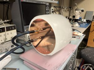
Testing a patch antenna with the
RIC (Representational Ice Cylinder)
A circular patch antenna was designed in the VHF/UHF spectrum to optimize puck surface area and thickness. It features orthogonally positioned probes for circular polarization. Simulation software ensured consistent performance in air and ice, and a dielectric matching layer was added to address potential inconsistencies. The design, made using PCB techniques, used Rogers RO4360G2 for both substrate and superstrate with a dielectric constant of 6.15.
The antenna’s air performance was measured at the University of Colorado Boulder, yielding consistent results between chamber readings and simulations.
Ice performance, assessed using a representative ice cylinder (RIC), influenced the 413 MHz transmission frequency selection for the in-ice test.
HF Crossed-Loop Antenna
A crossed-loop antenna was developed in the HF spectrum from 7/8″ ferrite rods, forming a 10” by 10” cross, with one rod being solid. This design, using a 90-degree phase shift network, achieves up/down circular polarization optimized for a 5MHz RF signal.

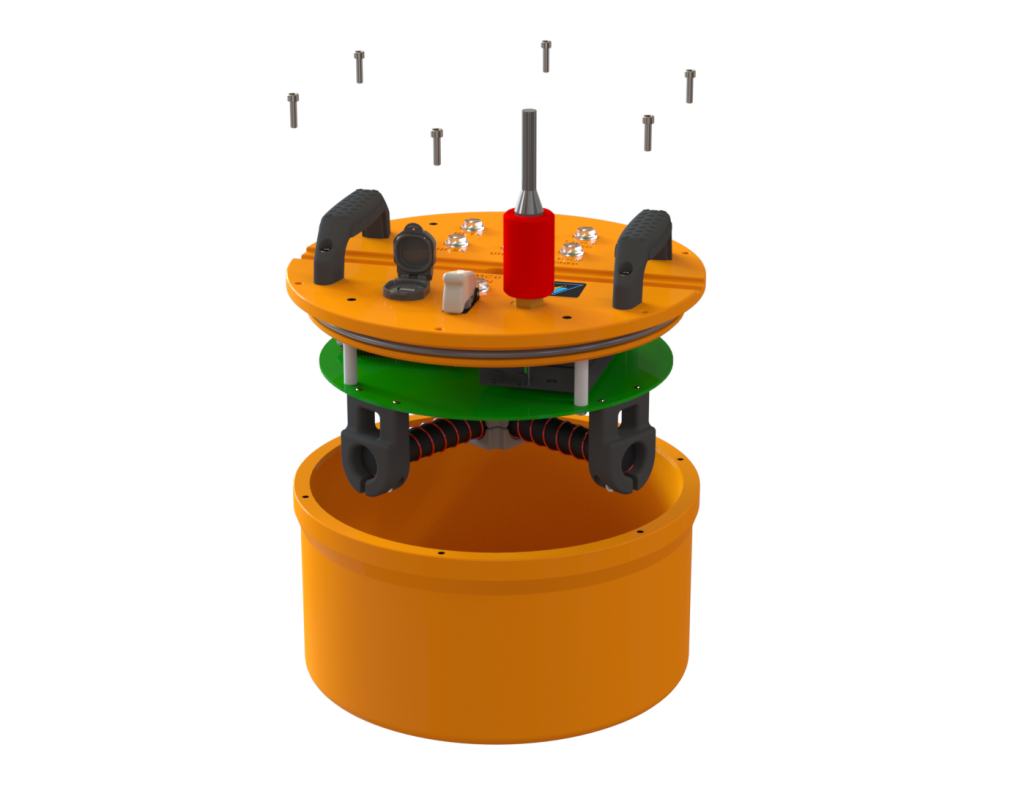
Rendering showing internal boards and crossed-loop antenna
An HF loop tuning sensor was integrated for resonance, working alongside a tuning capacitor bank. A 1 Watt Class-E amplifier, designed in LT Spice, required a 0.9uh inductance for optimal driving. The initial test of the FAM board highlighted power delivery inefficiencies, prompting modifications. After adjustments, the board achieved an 87.1% efficiency at CU-Boulder. Further tests on the board’s loop tuning networks are underway.
In-ice testing, UHF and HF Antennas

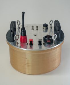
Fully assembled puck.
The UHF patch and HF crossed-loop antennas are set for ice testing through approximately 500 meters of glacier ice. Initially, the radio frequency communication pucks were planned as two separate designs for each antenna type. Yet, merging both into a unified prototype puck design was deemed beneficial, streamlining hardware and easing field operations.
The prototype puck design features a modular design, 30 cm in diameter by 22 cm in height, addressing the challenges posed by the testing conditions, including low temperature tolerance, water resistance, ease of handling and securing to the ice and effective thermal management.
The prototype puck consists of a 3D printed ULTEM housing and an aluminum lid, with all internal electrical components attached to the underside of the lid for heat rejection to ambient. The crossed-loop antenna is suspended by five standoffs, keeping a minimum of 2.54 cm distance between any large ground planes such as the patch antenna and the FAM board. The patch antenna is attached to the bottom of the puck, for direct contact with the ice. The user interface sits on the top of the lid, with LEDs to indicate operational status, a USB port for programming the antennas and for data access, a main computer power switch, and a battery power port.